
The bridge deck is the most critical element of any bridge structure. As the surface directly supporting vehicle traffic, pedestrians, or rail lines, it serves as the primary interface between live moving loads and the supporting superstructure below.
Designing a bridge deck system is a complex balancing act. Engineers must ensure the deck handles heavy dynamic forces and harsh weather exposure while keeping structural weight manageable for piers and foundations.
Here are the primary technical considerations structural engineers evaluate when designing modern bridge deck systems.
1. Load Capacities: Dead Loads vs. Live Dynamic Loads
Bridge decks must support two distinct types of structural forces under strict design codes (such as AASHTO or Eurocodes):
- Dead Load: The permanent self-weight of the deck slab, wearing surface, barriers, utilities, and sign gantries. Engineers aim to minimize dead weight, especially on long-span bridges, so the primary structure can allocate more capacity toward moving traffic.
- Live Load & Dynamic Impact: The temporary forces exerted by heavy trucks, buses, or trains. Engineers apply dynamic load allowances (impact factors) to account for vehicle bouncing, sudden braking forces, centrifugal forces on curved bridges, and vibration over time.
2. Selection of the Deck Type and Material System
The choice of deck material dictates the bridge’s structural weight, construction speed, and overall lifecycle cost:
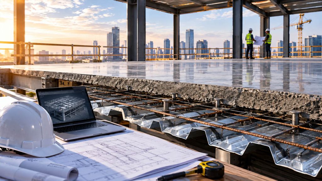
Cast-in-Place Reinforced Concrete Slabs
The traditional choice for short- to medium-span bridges. Cast-in-place concrete offers high stiffness, excelente durability, and seamless integration with supporting girders, though it requires extensive formwork and curing time on-site.
Precast Full-Depth Concrete Panels
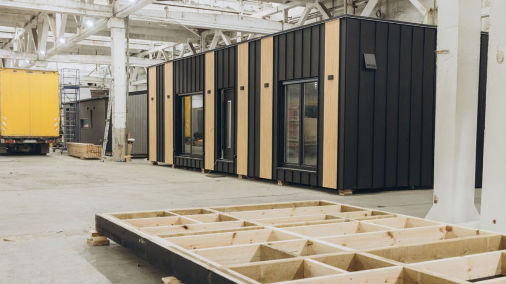
Fabricated off-site in controlled factory conditions, precast panels are lifted into place and joined using ultra-high-performance concrete (UHPC) grouted joints. This system drastically speeds up construction and minimizes traffic disruptions during deck replacements.
Orthotropic Steel Decks
Consisting of a flat steel plate stiffened by longitudinal ribs welded underneath, orthotropic decks are exceptionally light and strong. They are frequently specified for long-span cable-stayed or suspension bridges where minimizing dead weight is paramount.
Fiber-Reinforced Polymer (FRP) Composite Decks
Lightweight and highly corrosion-resistant, FRP modular decks are increasingly specified for bridge rehabilitation projects where an existing superstructure needs an increased live-load rating without adding weight.
3. Drainage, Cross-Slopes, and Hydrology
Water is the single greatest threat to a bridge deck’s lifespan. Standing water creates hydroplaning hazards for motorists and accelerates the chemical deterioration of deck materials.
Engineers incorporate precise cross-slopes (typically a 2% gradient from the center crown to the outer edges) and longitudinal grades to channel runoff toward drainage scuppers. Drainage systems must be designed to discharge water cleanly away from underlying steel girders, piers, and substructures to prevent localized corrosion.
4. Corrosion Protection and Environmental Resistance
Bridge decks are constantly exposed to moisture, airborne salts in coastal regions, and aggressive de-icing chemicals in winter climates. Chlorides penetrate porous concrete and corrode internal steel reinforcement, causing spalling and structural breakdown.
To combat environmental degradation, engineers specify multiple defense layers:
- Epoxy-Coated or Stainless Steel Rebar: Prevents corrosion even if moisture reaches the reinforcement depth.
- Low-Permeability Concrete Mixes: Integrating fly ash, silica fume, or slag cement densifies the concrete matrix, blocking moisture penetration.
- Protective Waterproofing Membranes: Applied beneath the asphalt wearing surface to form an impermeable barrier over the concrete slab.
5. Thermal Expansion and Expansion Joints
Bridges expand and contract continuously due to daily and seasonal temperature swings. Without proper engineering accommodations, thermal movement creates massive internal stresses capable of cracking concrete or buckling steel members.
Engineers position expansion joints (such as strip seals or modular joints) at designated deck intervals to absorb longitudinal thermal movement while maintaining a smooth riding surface. On modern integral bridges, engineers eliminate joints entirely by designing flexible abutments that absorb movement, removing a common point of water leakage and maintenance failure.
6. Fatigue Resistance and Structural Redundancy
A bridge deck undergoes millions of stress cycles over its intended 75- to 100-year lifespan. Repeated heavy axle loads cause micro-cracking in concrete and metal fatigue in welded steel joints.
Engineers run detailed finite element analysis (FEA) models to evaluate fatigue limits. Designing structural redundancy into the deck ensures that localized damage or micro-cracking will not lead to catastrophic structural failure, giving maintenance crews time to perform repairs.
7. Constructability and Maintenance Access
A bridge deck design is only successful if it can be safely built and maintained. Engineers evaluate how deck elements will be delivered, lifted, and secured on-site under tight spatial constraints.
Designers also incorporate future maintenance needs directly into the initial plans: inserting embedded sensors to track structural health, creating access hatches for inspection crews, and designing wearing courses that can be milled and replaced without damaging the underlying structural slab.
Engineering for Lifelong Performance
Bridge deck design represents an intersection of structural mechanics, material science, and environmental protection. By carefully balancing dead weight, traffic loads, waterproofing, and constructability, structural engineers create durable deck systems that keep transportation networks moving safely for decades.